Sunday, October 28, 2012

R2 won't be ready for Halloween but progress continues

We won't be ready in time for Halloween

With Hurricane Sandy making its way up the East Coast, plus the failure of the van's battery, we won't make it.  Even if the battery were replaced, we still face the obstacle of having to drive it on a hurricane soaked yard.  I've done that before and the van sank quickly!  Toss into that my left hand is still on the mend, so man-handling a very heavy R2-D2 is probably not a good idea.

Having said that, I have made some more progress on R2!

With the new frame and skins modified, I ran into another issue with them...they were not lining up properly where the center vents meet...

If you look closely, the vent rail on the right side is visible

Close up...the vent rail should be behind the skin
 The fix is awkward, drill new holes so that it will fit behind the skins.


Next up was the two 5 inch by 5 inch side pieces that cover the gap between the skins.  I had previously sanded, primed and painted them.  I lined them up in the frame, drew a line where they met the top of the bottom ring and used silicone to bond an L bracket to it.


I'd rather have screws show from the bottom, which I can later trim off and cover up with touch up paint.  Three 5/32 holes and threaded for 10-24 machine screws

Installed.  Since it is held in place with silicone, it has some play but too much and it will pop off.

Both pieces in.  Too firm this up, I will use servo tape (double sided tape) on an L bracket to secure the panels in their proper position.
 When tweaking, you run across pieces that were problematic the first time.  In that case, the internals for one of the center vents was a real challenge.  It took quite a bit of time to dismantle and attempt to repair.  I'll eventually replace these with new internals.

The bottom vent required a lot of JB Weld to re-attach and secure.  The bolts on the sides hold the vent surrounds in place, another area requiring ongoing work.
 And here's how R2 looks now...slowly coming back to its old self!


Sunday, October 21, 2012

Dome drive install and skin servos removed

Today I spent some time on R2-D2 #1  With Halloween 10 days away, its crunch time to get our little buddy back together to greet the kids!

As I mentioned last time, the skins had a minor problem.  The servo brackets I had worked so diligently to install into the skins were not going to work out.  They stick out inside the body but with the new frame, a large structural piece is now there where it was not on the old frame.

That meant I had to re-think how all the servos and linkages would pan out all over again.  And I think we'll come back to that a bit later, as time permits.  So, for now, I opted to disconnect all the servo linkages, servos and then cut free the servo brackets.

Due to the wider, and stronger, shoulders, the side mounted servo brackets won't work on this frame.

To prevent damage to the hinges and doors, I removed the linkages.

Linkages, and servos removed

Before the skins were bonded together, I had threaded the servo bracket holes and bolted them into the inner skin.  However, now that all has to go and there's no way to access the screw head inside the skin

I though of this ahead of time, using rubber spacers between the skin and bracket, just in case I had to use a hacksaw blade to cut them off...

Skins now have servo brackets removed
 I did a test fit and noticed another "Hmmm" item...

For some reason, the right side, the vent support piece is visible.  While the skins seem centered up fine, I'll probably have to re-align the vent surround piece to cure this
 Next up was installing the dome drive.  The dome drive is a 12v motor that contains a wheel hub and makes contact with the dome rockler bearing, causing it to move.  Placing it so its not in the way of other things, like R2's gadgets that come out the front door, a bit complicated.

Since the dome drive hangs under the top frame ring, the screws need to be countersunk, so the rockler bearing sits flush on the frame ring...


Kind of a confusing pic...Two flush mounted screw heads...next to a flush mount frame rod machine screw too.

After some fine tuning, the drive wheel is adjusted, a tension spring is added and the dome drive is installed and working


Sunday, October 14, 2012

Progress update


I'm making steady progress of both droids but R2-D2 #1 is back upstairs, where i can begin re-assembling all the electronics that were removed.

R2 has the second droid's frame, which uses the newer JAG v5 frame.  It also sports a 2-3-2 mechanism and 2 linear actuators that will allow the body to pivot.  At a later date I will have a center foot lift device so R2 can stand on his two outer legs or transform into the 3 leg driving mode.

I installed the rockler bearing onto the frame the other evening, which required using the digital micrometer to figure out the exact center.


Next up, I was looking over the old front skins and checking to see about mounting them onto the new frame.  Well, the large door servos will require some tweaking as the new frame will not allow those to work in their present position.  The side frame pieces are much larger on this frame and the servos present position will not work.

That's the latest

Monday, September 3, 2012

A little delay in the R2 refit !

Well I haven't posted any blog updates for a few weeks, so let's catch up.

Back in June I had decided to take R2-D2 apart completely because I noticed a slight wobble and pronounced squeak in the lower shoulder area.  It turns out that the modifications I had made to the frame was to blame.  The frame rod I had placed under each shoulder worked its way loose, thus the wobble and squeak.

My plan was to rebuild R2 with the newer design frame, the JAG v5 that my second R2 has.  I obtained some help from my friend Fred and his CNC machine to make new frame rings.  I could re-use the vertical frame rods from the original frame to the new one.

Then I started to completely dismantle the old frame and assemble the new one.  The frame rods are attached from the ends and have a threaded hole for the machine screw to fasten them.  I encountered a few that were pretty tough to move.  As I pieced the new frame together, I had one rod not go in correctly (cross thread), so I attempted to remove it.  I twisted and tugged and it wouldn't budge.  So I put both hands on it and attempted to crank it loose.

I heard a pop and thought the frame rod had finally come out.  Then I noticed my left hand, mostly my thumb.  Below the knuckle on down to the joint with the hand, it was extremely swollen and turning blue.  It didn't hurt...but I also couldn't move it.  I paused, went upstairs for an ice pack and iced it for a few minutes.  When I noticed it wasn't improving, I texted a nurse friend for advice.  After a few messages, it was pretty obvious a trip to the Emergency Room was in order.

As I walked out to my car, ice pack in hand, it dawned on me that my Honda Civic and its manual transmission might be a bit much to handle.  I opted to take the Odyssey (minivan) instead, with its automatic transmission making the one handed drive a lot easier.

Now we've all made a trip to the Emergency Room in the late evening.  We expect a huge line, a wound that isn't as bad as it really is, get a splint and an ibuprofen and call it a night.  That's truly what I expected.  As I checked in and waited in the waiting room, I noticed that the wound was still extremely swollen.  I've never broken a bone but based on what I know about the symptoms, this didn't meet them.

Explaining to the triage nurse, then the PA, and then the radiology staff what happened was memorable.  I explained, very matter of factly, that I was working on my R2-D2's frame and heard my thumb pop when I tried to unthread a stuck frame rod.  It was priceless to watch them busily jot down notes and just stop completely.  (I'm sure many a transcriptionist had to do a double take, too).

The xrays came back with no break, which wasn't good news, they told me.  The PA gently moved my thumb side to side, THAT hurt.  He grimaced and said it looked like Gamekeeper's Thumb and I will have to see the hand specialist.  Since it was late (11:30pm), they wanted me to see him at 8am.

I went hope in a splint and pain meds I couldn't take or I'd never wake up in time for the hand specialist.

At 8 I was at Bangor Plastic and Hand.  I've been here a few times before, I burned my left hand as a baby and Dr. Branch has done some procedures to improve range of motion in that hand.  I got right in and after he numbed up my hand and thumb (with the biggest needle ever!), he started to examine and move it around.  Since I love needles and already felt awesome, I wasn't looking.  However, based on the expressions of his assistant, it was really messed up.  He explained the injury and what was involved with repairing it.  

And I was only slightly nervous, up until I was being scheduled for surgery the next day and words like "pin" and "anchors" were mentioned.  They noticed I was fading out and getting really pale, so they decided to lay me down.   After some paperwork, it was off to work to and inform them of what's going on.

The next day, I had the surgery to repair the torn ligament in my hand.  

Post Op, nice cast, don't you think?


Since its a ligament, it will be a really slow heal.  That will certainly put a damper on some of the things I planned to do to my droids. 

Since surgery, I am now in a much smaller cast that protects the thumb from the base to the knuckle.  Physical Therapy has begun and just simple tasks like making a "4" hand sign or touching the tips of my fingers is still a challenge.

However...despite the injury, I have still been at it.  I've basically grabbed up parts and pieces from the second R2 to re-build the first.  Plus many tweaks I have wanted to do.

Using the 232 system from the second droid, white backplate behind arms, new small speakers behind vents....
 
Charging port version 1 being tried out
 
 More soon!


Tuesday, July 3, 2012

Detail pieces atached to resin booster rocket assembly

Today the weather was bright, sunny and warm so once I got home from work, I dove into getting the remaining detail pieces painted.


I probably should have let the pieces dry for 24 hours but after 4 hours in direct sunlight, they seemed ready to go.  Removing he tape manged to remove some paint too....but nothing too bad.  (R2-D2 has been through how many wars now?)

There's a dimple in the back showing where the 6/32 thread hole needs to be made.  Pretty quick work..you can see in the screw head that holds the leg strut piece molded into the piece.


A 6-32 hex head screw, with a lock washer and washer helps hold it all in.


Here's how the booster covers look lined up...


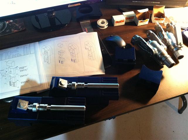
And here's how my desk looks with all these beautiful pieces!


Jerry (JAG, the gent who designed and had this all made in aluminum) contacted me to let me know he had extras of the aluminum trays that the assembly attaches do and is mounting inside the leg.  That will help a lot!

What next?

Well, once the legs have the proper opening cut into them and the tray pieces arrive, I can check for fit...and try to figure out how to make the middle section disappear as it does in the movie...granted, all movie magic!
 

Monday, July 2, 2012

Piecing the silver and blue together

Tonight I did some quick work on the blue booster cover and silver leg strut piece. 


First I had to drill out the holes for the 6-32 screws to pass through.  The resin piece clearly shows the spot to drill, so no real guess work here


The leg strut piece needs a quick sanding, then drilled and tapped for a 6-32 thread hole.  Since it takes a bit of distance to get a good thread started in a shallow hole like that, I opted for a longer 6-32 screw than the 1/4 inch ones the plans use.


Then I had that "Oh [colorful metaphor]" moment.  I realized on the top leg strut piece, I painted it all silver when only the center square should be.  So, I taped up the area that does not need blue paint and will work on priming and doing the blue formula on that area...


So, a slight delay since this will take 24 hours for the paint to cure once done.  But, an easy enough fix.
 

Sunday, July 1, 2012

More Resin Booster work

Today I dedicated some more time to working on the resin boosters.

One of the first things I had to do with the mounting blocks is cut off the 1/4-20 screw plunger as they were molded installed.


After some careful cutting with a hacksaw....


The screw plunger needs to be tapped for a 1/4-20 thread and the hole next to it, for a 10-24.  One of my favorite bookmarks I have even printed out is THIS , this tells you what size drill bit you will need to tap a certain thread. 


I checked and double checked the which way the booster arms should be and screwed the mount to them.


Next up was drill and tapping for the boosters themselves.  I gently drill a hole (5/32 drill bit and then tap it for a 10-24 thread.


The caps require some additional sanding to remove an excess resin from he molding process.  There goes all that beautiful paint again!  I found having two pieces of sand paper laying on the work bench ideal, assuring a flat/level finish.


The plans call for a 3/8th of an inch long 10-24 screw but found that to be a bit too short.  I replaced it with a 1/2 inch long one and it worked nicely.  Since the inside of the booster rocket is hollow, any excess thread goes inside.


Next up was the booster seating block.  Pretty straight forward, drill two 5/32 holes in each and tap, right?


The pieces need a bit of work to make level/flat.  There is a bit of a seam line in the resin piece, which just requires a hacksaw to trim away, then sand down with some rough sandpaper and some finer stuff after.


To keep things level, I'm using a vice to make sure the holes are tapped straight.  (This is also why I am using the drill press instead of a hand drill)


This is the booster female connector and cast as it is, it can be a little difficult to understand.  First, we replaced the pivot shaft with something off the shelf, so we need to make a hole that it will fit.  In this case, a 7/32 hole allows it to pass thru.  At first glance, I didn't catch that the top hole not only goes all the way thru but wide enough for the entire head of the 6/32 socket head screw to got inside. 


The rocket booster has a dimple showing where the hole should be.  Using a 7/64 drill bit, the hole is made and tapped for a 6/32 thread.  Here you can see the top of the socket thru the piece.


The booster slider needs a hole made and a screw to secure the assembly, so that they do not pop out.  I couldn't find a way to mimic how the aluminum version has a spacer inside, since the resin version isn't as smooth.  I opted to drill a 7/64 hole straight thru and use a 4-40 sized screw and lock nut (nylon insert).  Since this is resin, I left a little bit of play, maybe a 1/16th of an inch.  Too tight would crack it.


Here's how the assembly goes together.  The flat-head screw piece you see threads into the other piece nicely.


Here's how it all looks now...


Now the hard part remains!  I do not have he mounting piece, nor a blue print for it so I am hopeful to obtain some details.  The mounting blocks should have 10-24 threaded holes that line up with holes in the legs.  Lacking that information, I haven't [wisely] drilled holes in my aluminum legs yet!

So far I am extremely envious of those who have the aluminum version!  No worries about drilling and tapping holes into very small and precise parts!

That said, this is a lot of fun to take on.  Soon, we'll be working on how to make these pieces move, opening and closing.