Today the weather was bright, sunny and warm so once I got home from work, I dove into getting the remaining detail pieces painted.
I probably should have let the pieces dry for 24 hours but after 4 hours in direct sunlight, they seemed ready to go. Removing he tape manged to remove some paint too....but nothing too bad. (R2-D2 has been through how many wars now?)
There's a dimple in the back showing where the 6/32 thread hole needs to be made. Pretty quick work..you can see in the screw head that holds the leg strut piece molded into the piece.
A 6-32 hex head screw, with a lock washer and washer helps hold it all in.
Here's how the booster covers look lined up...
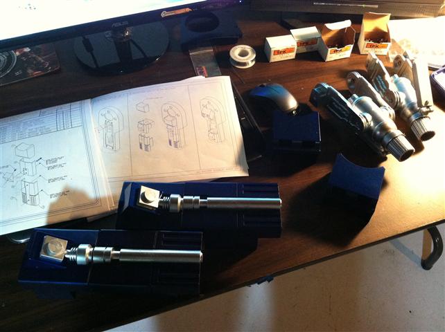
And here's how my desk looks with all these beautiful pieces!
Jerry (JAG, the gent who designed and had this all made in aluminum) contacted me to let me know he had extras of the aluminum trays that the assembly attaches do and is mounting inside the leg. That will help a lot!
What next?
Well, once the legs have the proper opening cut into them and the tray pieces arrive, I can check for fit...and try to figure out how to make the middle section disappear as it does in the movie...granted, all movie magic!
Tonight I did some quick work on the blue booster cover and silver leg strut piece.
First I had to drill out the holes for the 6-32 screws to pass through. The resin piece clearly shows the spot to drill, so no real guess work here
The leg strut piece needs a quick sanding, then drilled and tapped for a 6-32 thread hole. Since it takes a bit of distance to get a good thread started in a shallow hole like that, I opted for a longer 6-32 screw than the 1/4 inch ones the plans use.
Then I had that "Oh [colorful metaphor]" moment. I realized on the top leg strut piece, I painted it all silver when only the center square should be. So, I taped up the area that does not need blue paint and will work on priming and doing the blue formula on that area...
So, a slight delay since this will take 24 hours for the paint to cure once done. But, an easy enough fix.
Today I dedicated some more time to working on the resin boosters.
One of the first things I had to do with the mounting blocks is cut off the 1/4-20 screw plunger as they were molded installed.
After some careful cutting with a hacksaw....
The screw plunger needs to be tapped for a 1/4-20 thread and the hole next to it, for a 10-24. One of my favorite bookmarks I have even printed out is THIS ,
this tells you what size drill bit you will need to tap a certain thread.
I checked and double checked the which way the booster arms should be and screwed the mount to them.
Next up was drill and tapping for the boosters themselves. I gently drill a hole (5/32 drill bit and then tap it for a 10-24 thread.
The caps require some additional sanding to remove an excess resin from he molding process. There goes all that beautiful paint again! I found having two pieces of sand paper laying on the work bench ideal, assuring a flat/level finish.
The plans call for a 3/8th of an inch long 10-24 screw but found that to be a bit too short. I replaced it with a 1/2 inch long one and it worked nicely. Since the inside of the booster rocket is hollow, any excess thread goes inside.
Next up was the booster seating block. Pretty straight forward, drill two 5/32 holes in each and tap, right?
The pieces need a bit of work to make level/flat. There is a bit of a seam line in the resin piece, which just requires a hacksaw to trim away, then sand down with some rough sandpaper and some finer stuff after.
To keep things level, I'm using a vice to make sure the holes are tapped straight. (This is also why I am using the drill press instead of a hand drill)
This is the booster female connector and cast as it is, it can be a little difficult to understand. First, we replaced the pivot shaft with something off the shelf, so we need to make a hole that it will fit. In this case, a 7/32 hole allows it to pass thru. At first glance, I didn't catch that the top hole not only goes all the way thru but wide enough for the entire head of the 6/32 socket head screw to got inside.
The rocket booster has a dimple showing where the hole should be. Using a 7/64 drill bit, the hole is made and tapped for a 6/32 thread. Here you can see the top of the socket thru the piece.
The booster slider needs a hole made and a screw to secure the assembly, so that they do not pop out. I couldn't find a way to mimic how the aluminum version has a spacer inside, since the resin version isn't as smooth. I opted to drill a 7/64 hole straight thru and use a 4-40 sized screw and lock nut (nylon insert). Since this is resin, I left a little bit of play, maybe a 1/16th of an inch. Too tight would crack it.
Here's how the assembly goes together. The flat-head screw piece you see threads into the other piece nicely.
Here's how it all looks now...
Now the hard part remains! I do not have he mounting piece, nor a blue print for it so I am hopeful to obtain some details. The mounting blocks should have 10-24 threaded holes that line up with holes in the legs. Lacking that information, I haven't [wisely] drilled holes in my aluminum legs yet!
So far I am extremely envious of those who have the aluminum version! No worries about drilling and tapping holes into very small and precise parts!
That said, this is a lot of fun to take on. Soon, we'll be working on how to make these pieces move, opening and closing.